Induction-extraction
- Details
- Parent Category: Maintenance Guide
- Category: Induction-extraction
Zenith WIA and WIP Series Carburetters
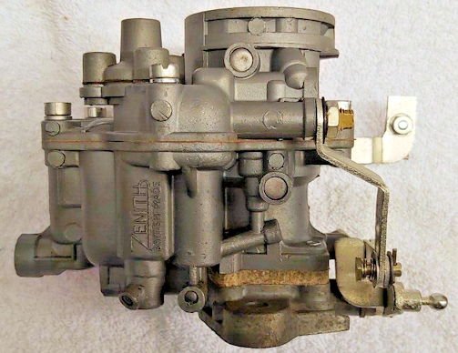
Zenith WIA and WIP Series Carburetters Features:
The following sections describe features and variations which are specific to models within the series WIA and WIP Carburetters, downdraught type having four main body assembly features, these are:
Upper barrel and float chamber cover. Main Body - Lower barrel, choke tube and float chamber. Throttle Body/Attachment Flange Assembly. Flanged Heat Insulator Block.
A mechanically operated accelerator pump, automatic strangler and lever type float are used. The purpose of the insulator block is to reduce the conduction of heat from the manifold to the float chamber: and so reduce the possibility of fuel vapour-lock occurring. Some models incorporate a depression incorporated power jet. The basic unit sizes are 34, 36 and 42 mm diameter choke. Variations in model detail are indicated in the type letters as shown here:
TYPE VARIATIONS
WIA
Initial Model. Three screw throttle body fixing.
WIA-2
Four screw throttle body fixing.
36 WIA-3
Air regulating screw. (NOT volume control screw).
42 WIA
Initial model.
42 WIA-2
Special short throttle body.
42 WIAT
As 42 WIA but with thermostatically operated strangler.
42 WIATD
As 42 WIAT but with throttle damper (for automatic gearbox).
36 WIP
Initial model. P indicates power jet omitted. Three screw throttle body fixing.
36 WIP-2
Four screw throttle body fixing.
36 WIP-3
Air regulating screw. (NOT volume control screw).
Dismantling and Assembly:
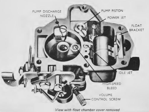
Remove float chamber cover retaining screws and lift off the cover to expose float chamber;this will give access to the Idle Tube High Speed Bleed, Accelerating Pump, Power Jet Float Needle, and Seating. The Main Jet is accessible after removing the Plug from beneath the float chamber; do not damagesealing ring and jet when removing them. If accelerating pump inlet and outlet valves are removed, take out the non-return ball valves beneath them for safety, otherwise they may drop out and get lost!
On assembly take care that the gaskets and power jet diaphragm are undamaged and that parts are correctly positioned when replacing the covers; make sure that the main discharge jet is replaced with the row of holes On the underside. When finally tightening the float chamber cover screws, do so in opposite and alternate pairs.
Petrol Level:
Generally speaking in 34 and 36 mm models (fuel inlet to float chamber bowl) the petrol level should be 16 mm (0.625 in) below the top face of the float chamber; where variations from this occur, the different level will be specified. When checking the level make sure that the carburetter is horizontal and that the float bracket is held down in its locating slot, to counter the float buoyancy.In the 42 WIA-2 models (fuel inlet to float chamber cover) the fuel level is 19 mm (0.75 in) below the top face of the float chamber.
Thermostat Unit for Air Strangler Control:
The use of a thermostatically operated strangler gives automatic choke control for cold-starting without need for the more usual manual method. The unit comprises a slef-contained assembly, fixed to the carburetter body, and engaging the strangler spindle; choke control is obtained by a combination of forces acting on a bi-metallic coil spring the outer end of which engages the strangler spindle operating lever. Constructional features, detailed method of operation and adjustments are as fully described for the Series VNT carburetter.
Idling Mixture Control:
Normally idling mixture variation is obtained by the Volume Control Screw mounted in the side of the Main Body, but those carburetters having the in the type designation (e.g. 36 WIA-3) have Air Regulation Control. The screw for this adjustment is located in the float chamber cover.
Accelerating Pump:
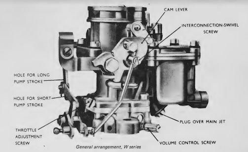
Most models use the normal interconnecting link/lever operation of the accelerating pump. On some 36W units
however, a cam is used instead of the direct linkage. The profile of the cam is such that the greater proportion of the discharge from the pump occurs during the early part of the throttle movement; this is required on particular applications to obtain the best possible acceleration. (Certain applications of the W series include a modification which provides for a degree of enrichment of full throttle high speed mixture strength by drawing fuel from the pump circuit at times other than when accelerating.)
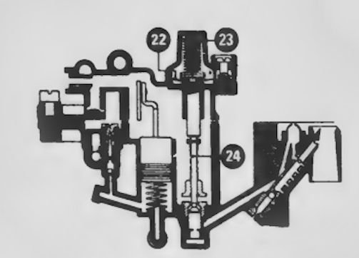
Power Jet :
Power jets 22, 23, 24, are fitted in WIA models; the jet is operated by diaphragm . control from the engine depression. At low throttle openings (high depression) the jet is closed; when the throttle is opened the depression is reduced, permitting the power jet to be opened by the diaphragm spring, allowing additional fuel to be fed to the main discharge jet.
Float Chamber Ventilation:
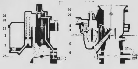
Ventilation of the float chamber is provided for in various ways. In some models this may take the form of an internal vent connecting with an impact tube projecting at an angle into the air intake and adjacent to the strangler flap. A simpler method consists of a direct ventto atmosphere via a groove cut in the float chamber cover. In the case of the 42 mm unit shown in Fig.32 a covered vent 29, 30 is used. Throttle Damper (for Automatic Gearbox): Closure of the throttle to idling position normally results in rapid reduction in engine rpm but for smooth operation when an automatic gearbox is fitted it is necessary to slow down the final stage of engine speed reduction. This is achieved by use of a damper consisting of a simple bellows unit placed in the throttle linkage line; its action delays the final throttle closure and brings the engine to idling speed gently.
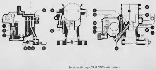
34 and 36W
1.Retaining screw
2. Accelerating pump piston
3. Inlet non-return valve
4. Throttle
5. Progression holes
6. Idling hole
7. Volume control screw
8. Air bleed hole
9. Discharge nozzle
10. Outlet non return valve
11. High speed air bleed
12. Idle tube
13. Float
14. Needle
15. Needle seating
16. Main jet plug
17. Throttle stop screw
18. Large venturi
19. Main discharge jet
20. Small venturi
21 Strangler flap
22. Power jet diaphragm
23. Compression spring
24. Power jet
Sections of 42W carburetter
2. Accelerating pump piston
3. Inlet non return valve
14. Needle
15. Needle seating
16. Main jet plug
19. Main discharge jet
25. Piston rod
26. Actuating rod
27. Link
28. Spring
29. Float chamber vent cover
30. Cover retaining screw
- Details
- Parent Category: Maintenance Guide
- Category: Induction-extraction
Zenith IZ Series Carburetter

A General Arrangement of the IZ Series Carburetter and internal features.The unit is a downdraught type, of compact design having a fully automatic strangler, accelerating pump and economy device.
The unit comprises two main assemblies, held together with five screws,Upper section comprising integral float chamber cover, fuel inlet connection and air inlet with strangler disc assembly.Lower section comprising integral choke, float chamber and attachment flange to engine, with throttle valve, jets, accelerating pump and economy device assemblies.

General Operation: The general principles of operation, adjustment, etc.,which are specific to the series.
Slow-running Tube : This incorporates a gauze filter to protect against blockage from dirt or other matter.
Accelerating Pump : A feature of this pump is the small bleed-back drilling from the pump chamber to the float chamber. Expanison of fuel due to heat soak-back can take place into the float chamber; otherwise dribble from the accelerator jet would occur.
The spring loaded non-return Ball Valve, of the Pump Jet. This prevents air bleed-back during the fuel re-charging suction stroke of the Pump Diaphragm and hence keeps the system primed.
Economy Device : Most economy devices operate to weaken the mixture by admitting extra air to the jet circuit. In contrast, the IZ Series operates to reduce the fuel supply to the circuit.For examination, remove the retaining screws and lift off the assembly and gasket; this will disclose the Economy Jet which can be removed with a screwdriver.Access to the internals is obtained by carefully removing the back plate which is secured to the cover by two cadmium plated screws. For replacing, assemble cover, internals and back plate first, then with gasket in place position the assembly on the main body and replace the fixing screws.

Dismantling: Disconnect external attachments; remove carburettey from engine. Undo the five cover retaining screws; remove float chamber cover . To obtain access to the Main Jet, lift out the float and pivot pin, and un-do the plug located at the base of the floatchamber, on the outside. The main jet can now be removed with a screwdriver through the plug-hole. Lift out the hook-shaped pump jet with its sealing ring; the Slow Running Tube can be lifted out and Emulsion Tube 10 can be unscrewed.
The Main Fuel Outlet Casting is NOT REMOVABLE. When replacing the float chamber cover, hold the strangler cam lever in the closed position until the cover is nipped down with centre retaining screws. Tighten screws evenly and securely from centre outwards.
Other points of dismantling and assembly will be selfevident.

— sections of IZ Series carburetter —
1.Strangler disc
2. Throttle valve
3. Progression holes
4. Idling hole
5. Volume control screw
6. Restriction
7. Main well
8. Filter gauze
9. Main fuel outlet
10. Emulsion tube
11. Slow running tube
12. Calibrated air bleed
13. Air jet
14. Accelerating pump jet
15. Ball valve spring
16. Delivery ball valve
17. Economy valve diaphragm
18. Return spring
19. Spring
20. Fuel valve
21. Economy jet
22. Calibrated restriction
23. Main jet
24. Non-return inlet valve
25. Spring
26. Accelerating pump lever
27. Pump diaphragm
28. Float
29. Needle valve and seating
30. Fuel inlet
- Details
- Parent Category: Maintenance Guide
- Category: Induction-extraction
Zenith Series 30 VIG, 36 AND 42 VIS Carburetters Guide

Guide to the Zenith Series 30 VIG, 36 AND 42 VIS type Carburetters.
Features:
This series of carburetters is used over a wide range of vehicles and industrial engines of one to larger four litres capacity. The constructional arrangement comprises two main assemblies:
1.Main Barrel, with Choke Tube, Strangler Disc, Throttle Valve, Economy Device and Integral Float Chamber Cover.
2.Float Chamber, with Jets, Accelerating Pump and Emulsion Block.
All models are of the downdraught type, but vary in a number of ways. Some have fully automatic stranglers for easy starting, others have semi-automatic stranglers. Similarly, the quality of the slow-running (idling) mixture is controlled in one of two ways. There are also variations in throttle control lever position, fuel pipe and ignition control connections, and accelerator pump action as summarised below:
30 VIG MODEL VARIABLES
- CARB Type 5
Replaces 30VIG—2 and 3 Fuel Connection 5/ 16 in O/d Pipe. Throttle control sometimes at the side of the carburetter
STRANGLER TYPE Semi-Auto. -IDLE MIXTURE CONTROL Volume Control - CARB Type 6
Fuel Connection 1/4 in o/d Pipe.
STRANGLER TYPE Fully-Auto. -IDLE MIXTURE CONTROL Volume Control - CARB Type 7
Fuel Connection 1/4 in o/d Pipe.
STRANGLER TYPE Semi-Auto. -IDLE MIXTURE CONTROL Volume Control - CARB Type 8
Ignition control connection tapped 7 x 1.0 mm thread.
STRANGLER TYPE Fully-Auto. -IDLE MIXTURE CONTROL Air Regulation - CARB Type 9
STRANGLER TYPE Semi-Auto. -IDLE MIXTURE CONTROL Air Regulation - CARB Type 10
Ignition control connection tapped 7 x 1.0 mm thread.
STRANGLER TYPE Fully-Auto. -IDLE MIXTURE CONTROL Air Regulation - CARB Type 11
Has special accelerator pump follow-up action
STRANGLER TYPE Semi-Auto. -IDLE MIXTURE CONTROL Volume Control
Each of the above types has a direct-acting fuel-level float, ignition control connection, automatic depression operated economy device, mechanically operated accelerating pump and strangler/throttle interconnection for fast idling. In some applications a mixture spreader-bar will be found across the choke, in the plane of the emulsion beak, in others an additional bar is formed by an extended choke retaining screw (as shown); alternatively a longer emulsion block beak may be used, without
spreader-bars. The arrangement found will be that which gives the best results for the air inlet flow characteristics of the engine type concerned.
The working features described apply generally to 36 and 42VIS models too, except that in these the Economy Device is mounted in the float chamber cover, and the Idling Mixture Control is by air regulating screw. Where-as most units have an alternative hole location for accelerator pump stroke adjustment, the 30VIG-11 uses an adjustable stroke limiting stop arrangement concentric with the piston rod, on top of the float chamber cover.This is used in conjunction with a spring-loaded throttle lever which converts a positive action pump into a follow-up type.

Diagrammatic section of carburetter
1. Economy valve spring
2. Full-throttle air bleed
3. Air passage
4. Capacity Well
5. Slow running jet
6. Strangler lever
7. Strangler disc
8. Air drilling
9. Needle valve and body
10.Choke tube
11.Economy valve
12. Air drilling
13. Volume control screw
14. Float
15. Emulsion block
16. Fuel outlet
Economy Device:
On some applications it may have been found necessary to limit the air bleed to the jets at part-throttle. In these cases an orifice plug is fitted at the top of the capacity well to limit the amount of air from Passage 8, when the economy valve is fully open. The hole in the plug may
vary between 1.4 mm (0.055 in) and 4.0 mm (O. 157 in); if fitted as an original part, it should not be necessary to change the plug at a later date. A smaller orifice will offset the effect of the economy device to some extent, by enriching the mixture when the Economy Valve 11 is open but will have little influence when the valve is closed because at this condition the small permanent AirBleed 2 is the controlling feature.

Petrol Level:
The correct fuel level, with the float holding the needle valve closed against a delivery pressure of 1.5 lb/sq.in is 17 mm (1 1/16 in) down from the top face of the float chamber. This will be obtained if, when the cover is removed the petrol level is 22 mm (7/8 in) below the datum face; or 35 mm (1 3/8 in) with float also removed.

Dismantling:
The float chamber can be removed by first extracting the retaining bolts in the cover and supporting it underneath, withdrawing it horizontally from the body for about one inch. The float may now be removed exposing the assembly as shown in Fig.23. Where main and compensating jets exist with square recesses, they can be removed by using one of the float chamber retaining bolts which is squared off as a key for this purpose.
If the emulsion block is removed, on replacement check that the gasket is sound, tighten centre screws first, see that the aluminium seal washers are replaced on the three lower screws. The small hole adjacent to the head of the bottom screw is to assist in centre-punching to prevent the screw from working loose and dropping into the engine.
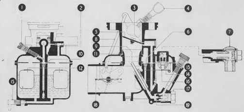
Diagram section of type 28G carburetter
1.Air regulating screw
2. (Inoperative)
3. Idling hole
4. Throttle stop screw
5 Throttle valve
6. Main air bleed
7. Fuel inlet with filter
8. Main discharge tube
9. Slow running jet
10. Choke tube
11. Dual floats
12. Needle valve
13. Needle valve and seat assembly
15 Float chamber drain
16. Float lever
17. Main jet plug
18. Strangler disc
19. Main jet
- Details
- Parent Category: Maintenance Guide
- Category: Induction-extraction
Zenith VN Carburetters

The Zenith Series VN carburetter overview and guide.
Features:
The Series VN carburetters are all downdraught types, having the following main body assembly features:
Main Barrel Assembly with Integral Floatchamber Cover.Floatchamber,Emulsion Block.
The unit sizes are based on 30, 32, 33, 34, 36, 37 and 42 mm diameter choke tubes. The basic design incorporates a depression operated economy device and a mechanically operated accelerating pump. There are however significant variations from the basic form and these are indicated by the change in type letter identification:

TYPE
- VNN Initial model
- VNN Economy Device and Accelerating Pump omitted
- VNR Speed Governor fitted
- VNT Thermostat Unit for Air Strangler Control
- VNP Economy Device omitted
Minor variations occur in some of the jet circuits. In the 42VN unit, the main and
compensating jet outputs are supplemented at high speed with additional fuel from Auxilliary Jet 29, or from a calibrated hole drilled in the emulsion block, over the main jet channel. Auxiliary Jet 29 is sometimes used in 32VN models. In some models the floatchamber is vented to the Air
Inlet Passage 12 but others vent to atmosphere directly.

Operation, Adjustment, Trouble Shooting:
Petrol Level:
The petrol level is determined by the float position when holding the needle valve closed against a fuel pump delivery pressure of 2.5 p.s.i. The float arm (or thickness of the needle seating joint washer) are factory set to give the following levels measured from the floatchamber top face.
FLOAT TYPE
Assembled unit METAL 18 mm 23/32 in
Floatchamber removed with float METAL 22.5 mm 7/8 in NYLON 26 mm 1 1/32 in
Float removed METAL 33 mm 1 5/16 in
Accelerating Pump:
The accelerating pump is of the typical mechanically operated plunger type, with a stroke limiting Pump Stop that enables a short or long stroke to be selected for summer or winter use respectively.
The pump stop fits loosely on the pump rod and is held in place on the floatchamber cover by a spring. A long, or a short projection on the stop may be positioned to limit the travel of the pump operating lever, by lifting the stop against the spring and rotating it a half turn to. select the appropriate position. (Long projection - short pump stroke; short projection - long stroke).
The pump is operated by a two-part lever arrangement connected by a tension spring. The spring gives a follow-up movement to the pump piston, so extending the period of accelerating fuel injection when the throttle is opened suddenly; also, it facilitates change-over of the pump stop.
- Details
- Parent Category: Maintenance Guide
- Category: Induction-extraction
The SU Type HD Design, construction. parts and identification.

The Type HD (Diaphragm-jet) carburettor was introduced after the original Type H version. It was manufactured now in larger sizes only — 1 1/2 in the HD4, 1 3/4 in the HD6 and 2 in HD8, and was therefore generally fitted to larger and heavier cars.The characteristic features of the Type HD are the methods of metering fuel for idling, and of sealing the jet base.
The Type HD Construction has the piston and suction chamber assembly is of the same general design as that of the original Type H. The dashpot bore may be either dustproofed or non-dustproofed, and may therefore have un-drilled or drilled piston damper caps respectively.
The float chamber assembly is of similar design to Type H, in that it houses a brass float sliding on a central spindle, and the inlet valve is closed by a hinged lever mounted in the detachable float chamber top. An ignition timing vacuum tapping is provided in the roof of the bore, the fine hole emerging at the edge of the throttle plate when in the closed position. The hole is bored through from a flat projection behind the suction chamber. Connection is made by an adapter plate with a stub pipe, secured to the body with two screws. A gasket is fitted between the body and the plate.

The jet slides within a bearing, secured to the underside of the body, by the same method as in the Type H, and is surrounded by an open-ended cylindrical housing, cast integrally with the body. The housing is closed by a jet housing, incorporating the jet actuating lever assembly hinged in integrally-cast lugs, and an extension of the float-chamber, the parts being secured to the body by four screws. A flexible diaphragm (fixed to the base Of the jet assembly) is clamped between the float Chamber extension and the underside of the jet
housing, and divides the housing cavity into two chambers. The upper chamber contains the jet actuating (lowering) mechanism and the lower chamber is linked to the float chamber via a drilling in the extension, and is therefore flooded with fuel. The fuel flows up through the hollow jet to the orifice at the top. A helical compression spring, fitted between a cup at the base of the jet assembly and a locating spigot in the float chamber extension, loads the jet upwards.
All HD4 and HD6 units are fitted with throttle spindle sealing glands, which minimise inwards air leakage when the spindle bearings become worn. Some HD8 units are also so equipped, while others have no sealing glands and are fitted with replaceable PTFE bushes. The glands have tapered faces, and are fitted into conical-ended counterbores in the unit body. A helical compression spring, retained by a steel sleeve pressed into the end of the counterbore, compresses the gland so that the bore closes Onto the throttle spindle and forms a seal. The glands do not require servicing, and no provision is made for their easy removal.

PTFE bushes are inserted into counterbores in the unit body from inside the bore of the unit. They are retained in position by circular spring clips fitted to the throttle spindle.
The underside of the body has cast ribs, and there is a cast projection at each side of the main bore. The ribs are internally-drilled to form a passage which bypasses the throttle plate when it is closed, One of the side projections houses a screwed needle valve, the end Of which intercepts the drilled passage, and functions as a slow running volume Screw. The Other side projection has a vertical bore in which slides a cam rod, forming part of the cold start enrichment/throttle opening interconnection mechanism. The top end of the cam rod is fitted with a plate, carrying an adjusting screw which bears on the throttle spindle arm. The bottom end is rivetted to an arm, at the end of which is a roller. The roller bears on a cam at the end of the jet actuating lever spindle.


