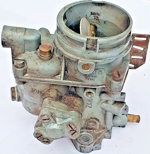
Zenith IZ Series Carburetter

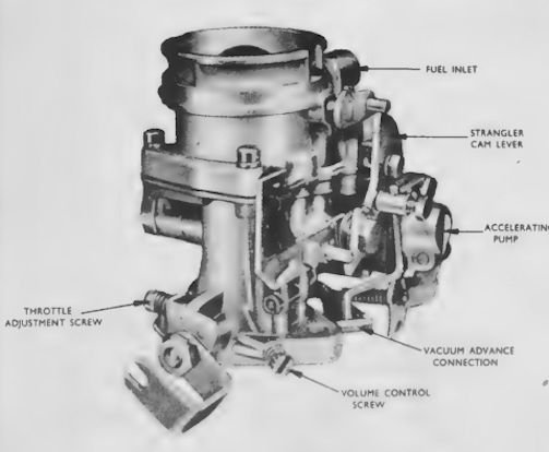
A General Arrangement of the IZ Series Carburetter and internal features.The unit is a downdraught type, of compact design having a fully automatic strangler, accelerating pump and economy device.
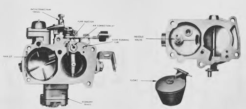
The unit comprises two main assemblies, held together with five screws,Upper section comprising integral float chamber cover, fuel inlet connection and air inlet with strangler disc assembly.Lower section comprising integral choke, float chamber and attachment flange to engine, with throttle valve, jets, accelerating pump and economy device assemblies.

General Operation: The general principles of operation, adjustment, etc.,which are specific to the series.
Slow-running Tube : This incorporates a gauze filter to protect against blockage from dirt or other matter.
Accelerating Pump : A feature of this pump is the small bleed-back drilling from the pump chamber to the float chamber. Expanison of fuel due to heat soak-back can take place into the float chamber; otherwise dribble from the accelerator jet would occur.
The spring loaded non-return Ball Valve, of the Pump Jet. This prevents air bleed-back during the fuel re-charging suction stroke of the Pump Diaphragm and hence keeps the system primed.
Economy Device : Most economy devices operate to weaken the mixture by admitting extra air to the jet circuit. In contrast, the IZ Series operates to reduce the fuel supply to the circuit.For examination, remove the retaining screws and lift off the assembly and gasket; this will disclose the Economy Jet which can be removed with a screwdriver.Access to the internals is obtained by carefully removing the back plate which is secured to the cover by two cadmium plated screws. For replacing, assemble cover, internals and back plate first, then with gasket in place position the assembly on the main body and replace the fixing screws.

Dismantling: Disconnect external attachments; remove carburettey from engine. Undo the five cover retaining screws; remove float chamber cover . To obtain access to the Main Jet, lift out the float and pivot pin, and un-do the plug located at the base of the floatchamber, on the outside. The main jet can now be removed with a screwdriver through the plug-hole. Lift out the hook-shaped pump jet with its sealing ring; the Slow Running Tube can be lifted out and Emulsion Tube 10 can be unscrewed.
The Main Fuel Outlet Casting is NOT REMOVABLE. When replacing the float chamber cover, hold the strangler cam lever in the closed position until the cover is nipped down with centre retaining screws. Tighten screws evenly and securely from centre outwards.
Other points of dismantling and assembly will be selfevident.

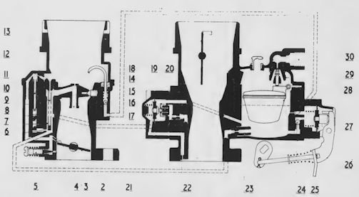
— sections of IZ Series carburetter —
1.Strangler disc
2. Throttle valve
3. Progression holes
4. Idling hole
5. Volume control screw
6. Restriction
7. Main well
8. Filter gauze
9. Main fuel outlet
10. Emulsion tube
11. Slow running tube
12. Calibrated air bleed
13. Air jet
14. Accelerating pump jet
15. Ball valve spring
16. Delivery ball valve
17. Economy valve diaphragm
18. Return spring
19. Spring
20. Fuel valve
21. Economy jet
22. Calibrated restriction
23. Main jet
24. Non-return inlet valve
25. Spring
26. Accelerating pump lever
27. Pump diaphragm
28. Float
29. Needle valve and seating
30. Fuel inlet
