Wheels & Brakes
- Details
- Parent Category: Maintenance Guide
- Category: Wheels & Brakes
Lotus Wheel Fitment PCD & Offsets
Size Guide

|
Model |
P.C.D. |
|
Lotus Eclat |
4 x 114.3 |
|
Lotus Excel |
4 x 114.3 |
|
Lotus Elite |
4 x 114.3 |
|
Lotus Esprit (Pre 1981) |
4 x 100 |
|
Lotus Esprit (From 1981) |
5 x 120 |
|
Lotus Esprit 2, 3 (Pre 1984) |
4 x 100 |
|
Lotus Esprit 2, 3 (From 1984) |
5 x 120 |
|
Lotus Exige |
4 x 100 |
|
Lotus Turbo |
5 x 120 |
See other Makes of car to see if they will fit. Make by letter A-Z
The bolt circle diameter (BCD), also called the pitch circle diameter (PCD).
 |
| 4 Bolt pitch circle diameter (PCD). |
 |
| 5 Bolt pitch circle diameter (PCD). |
To learn More View Car Wheels Hub sizing
A general guide to common bolt patterns by manufacturer:
BMW: 5x120 mm
Dodge: 5x100 mm, 5x114.3 mm
Ford: 4x108 mm, 5x114.3 mm, 5X135 mm, 5X139.7 mm
GM (Chevy, Pontiac, etc):5x100mm, 5x115 mm, 5x120.7 mm, 6X139.7 mm
Honda/Acura: 5x114.3 mm, 4x100 mm, 4x114.3 mm
Jeep Wrangler JK 07-UP 17"&18" 5x127mm 5x5in
Mazda: 5x114.3 mm, 4x100 mm
Nissan/Infiniti: 5x114.3 mm, 4x114.3 mm
Peugeot/Citroen: 4x108mm
Renault: 5x108 mm, 4x100 mm
Subaru: 5x100mm, 5x114.3mm
Toyota/Lexus/Scion: 5x114.3 mm, 5x100 mm
VW/Seat/Audi:5x100mm, 5x112 mm
- Details
- Parent Category: Maintenance Guide
- Category: Wheels & Brakes
Car Wheel Spinner knock-off History

The spinner on automobile wheels historically refers to knock-off hubs or center caps. They may be the actual, or intended to simulate, the design used on antique vehicles or vintage sports cars. A "spinner wheel" in contemporary usage is a type of hubcap or inner wheel ornament, that spins independently inside of a wheel itself when the vehicle is in motion, and continues to spin once the vehicle has come to a stop.
Original use
The spinner cap was introduced into the commercial vehicle and passenger automobile market in the 1930s.The spinner or "knock-off" was designed to keep the wheel on the automobile. They were screwed on and "knocked on tightly" using hammers and tools, hence the name "knock-offs". The driver's side wheel knock-off spinner of the auto's wheels were screwed on in a counter clockwise and the passenger side was screwed on in a clockwise so they would stay tightened as the auto was in forward motion. They were used until the development of the lug nut method attaching the wheel.
During the 1950s automobile manufacturers offered simulated wire wheel covers for a look of luxury that featured criss-crossing spokes designed to look like the real wire wheels that were used on vehicles in the 1920s and 1930s. These "spinner-wheel covers" were available on standard as well as featured on custom cars, and lowriders quickly adapted them for their own vehicles.
During the early-1960s, the simulated wire wheel covers returned, but with new look designed to emphasize sportiness with their radiating spokes and center "spinner caps." These classic center spinner caps feature a rigidly mounted propeller-like center element, usually with two or three projecting "blades." They were intended to simulate the knock-off hubs that were used on vintage racing vehicles and classic sports cars where a hammer or special wrench was used on the spinner to release or tighten the wheel to the hub.
These spinner hubcaps were most often an optional appearance upgrade to the standard equipment hubcaps or full wheel covers that attached to stamped steel wheels.
In the late 1960s, U.S. Federal safety standards banned the use of protruding bar spinners on automobiles.
Other uses
The mid-1950s Dodge four-bladed “spinner” wheel covers became an icons for the era and also became an item popular to owners to customize their cars.
Spinners were add on accessory marketed during the 1950s to decorate regular wheel covers for a custom look. Center spinner hubcaps were also available as original equipment from automakers.
Custom wheels for lowriders also used naked ladies on wheel covers and these were the first to feature a floating or spinner-type wheel device. A bracket was used to mount to the spindle so while the lady stood still the wheel spun around.Similarly, the Rolls-Royce Phantom has anti-spinners — the "RR" logo in the center of the hub is mounted on a spinner with an offset weight designed to ensure that the logo is always the right way up when the car is parked.
The hubometers used on large trucks, buses, and trailers that appear to be stationary while the wheel is turning to accurately measure the actual distance covered. They are actually enclosed and float in a liquid with anti-freeze as to be functional in severe low temperatures without freezing.
Modern concept
The modern spinner device is a decorative kinetic attachment to the wheel of an automobile. The spinner covers the center of a car's wheel and is designed to independently rotate by using one or more roller bearings to isolate the spinner from the wheel, enabling it to turn while the wheel is at rest.
- Details
- Parent Category: Maintenance Guide
- Category: Wheels & Brakes
Automotive Wheel alignment
Wheel alignment, sometimes referred to as breaking or tracking, is part of standard automobile maintenance that consists of adjusting the angles of the wheels so that they are set to the car maker's specification. The purpose of these adjustments is to reduce tire wear, and to ensure that vehicle travel is straight and true (without "pulling" to one side). Alignment angles can also be altered beyond the maker's specifications to obtain a specific handling characteristic. Motorsport and off-road applications may call for angles to be adjusted well beyond "normal" for a variety of reasons.
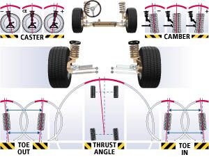
Primary angles
The primary angles are the basic angle alignment of the wheels relative to each other and to the car body. These adjustments are the camber, caster and toe. On some cars, not all of these can be adjusted on every wheel.
These three parameters can be further categorized into front and rear (with no caster on the rear, typically not being steered wheels) so summarily the parameters are:
- Front: Caster (left & right)
- Front: Camber (left & right)
- Front: Toe (left, right & total)
- Rear: Camber (left & right)
- Rear: Toe (left, right & total)
Secondary angles
The secondary angles include numerous other adjustments, such as:
- SAI (Steering Axis Inclination) (left & right)
- Included angle (left & right)
- Toe out on turns (left & right)
- Maximum Turns (left & right)
- Toe curve change (left & right)
- Track width difference
- Wheelbase difference
- Front ride height (left & right)
- Rear ride height (left & right)
- Frame angle
- Setback (front & rear)
Setback is the difference between right side and left side wheelbase length. It can also be measured as an angle. Setback less than the manufacturer specified tolerance (for example about 6mm) does not effect car handling. That's because, when the vehicle is turning, one wheel is ahead of the other by several centimetres and therefore the setback is negligible. There are even some car models with different factory setting for right and left side wheelbase length, for various design reasons. An off-spec setback may occur because of a collision or a difference between right and left caster.
Measurement
A camera unit (sometimes called a "head") is attached to a specially designed clamp which holds on to a wheel. There are usually four camera units in a wheel alignment system (a camera unit for each wheel). The camera units communicate their physical positioning with respect to other camera units to a central computer which calculates and displays
Often with alignment equipment, these "heads" can be a large precision reflector. In this case, the alignment "tower" contains the cameras as well as arrays of LEDs. This system flashes one array of LEDs for each reflector whilst a camera centrally located in the LED array "looks for" an image of the reflectors patterned face. These cameras perform the same function as the other style of alignment equipment, yet alleviate numerous issues prone to relocating a heavy precision camera assembly on each vehicle serviced.
- Details
- Parent Category: Maintenance Guide
- Category: Wheels & Brakes
Car Wheels Hub sizing

The wheel size for a motor vehicle or similar wheel has a number of parameters.
Bolt pattern
The bolt pattern determines the number and position of the mounting holes to allow the wheel to be bolted to the hub. As the bolts are evenly spaced, the number of bolts determines the pattern. For example: smaller cars have three (Citroën 2CV, Renault 4, some Peugeot 106s and Citroën Saxos, and the Tata Nano). Compact cars may have four bolts. Most United States passenger cars have five bolts. Pickup trucks and large SUVs can have as many as six, eight or ten.
Bolt circle
The bolt circle is the notional circle determined by the positions of the bolts. The center of every bolt lies on the circumference of the bolt circle. The important measurement is the bolt circle diameter (BCD), also called the pitch circle diameter (PCD).
This guide is accurate for most of the cars made by the listed manufacturers, but it is important to check and make sure before purchasing new aftermarket wheels.
The BCD may be expressed in millimeters or inches, and is usually given with the number of bolts. For example, a 1974 MG B has a 4/4.5 inch (4/114.3 mm) wheel hub, meaning it has a 4-bolt pattern with a 4.5 inch (114.3 mm) bolt circle diameter.
The most common BCD values are 100 mm (≈3.94 inches) and 4.5 inches (114.3 mm). Many old British cars use 4 x 4"
Special BCD values are: 95.25 mm (for MGF and Rover Metro), 98 mm (for Fiat group automobiles), 101.6 mm (for Mini, MG, Austin Metro), 100 or 105 mm (for some GM vehicles), 108 mm (mostly for PSA, Ford and Lincoln), 110 mm (for some GM vehicles), 112 mm (for Mercedes-Benz and some VW group vehicles), 115 mm (for some GM vehicles), 120 mm (mostly for BMW), 130 mm (for Porsche), 170 mm (for Saab 96). Old British Triumph cars used 4 x 3.75" using 3/8" studs. (7/16" or M12 studs are advisable for track use)
Determining the bolt circle
For a 4- or 6-bolt wheel, this measurement is merely the distance between the center of two diametrically opposite bolts. In the 4-bolt picture above, this would be the distance between holes #1 and #4, for example.
Some basic geometry is needed to find the center of a 5-bolt pattern. In practice, the BCD can be found by multiplying the center distance between any two adjacent holes by 1.701.
Generally, the BCD b can be calculated for any wheel from the number of bolts n and the center distance d between two adjacent bolts
A far easier way, using less math, is to take calipers and measure the hole size in the center of the wheel (note this dimension). Next measure the distance between the edge of the center hole and the center of one stud. Double this measurement and add it to the first. Job done! This method works with any number of studs.
Lug nuts or bolts
Wheels must be fitted with the correct type of lug nuts on wheel studs, or bolts. Lug nuts (aka wheel nuts in British English) are usually either flat, tapered (generally at 60 degrees and referred to as conical seat), or ball seats, meaning the mounting surfaces are flat, tapered, or spherical respectively.
Most Mercedes have ball lug seats from the factory while most aftermarket wheels have a tapered lug design. Wrong lug nuts for the wheel will not properly center it and cause wobble. Some manufacturers (e.g. Toyota and Lexus) have used taper lug nuts for steel wheels and flat seated lug nuts for alloy wheels.
Some aftermarket wheels will only fit smaller lug nuts, or not allow an ordinary lug nut to be properly torqued down because a socket will not fit into the lug hole. Tuner lug nuts were created to solve this problem by utilizing a special key to allow removal and installation with standard lug wrench or socket. The design of tuner lug nuts can range from bit style to multisided or spline drive, and are sometimes lightweight for performance purposes.
A variation is the "locking wheel nut", which is almost universally used for alloy wheels in the United Kingdom. One standard lug nut on each wheel is replaced with a nut which requires a special and unique key (typically a computer-designed, rounded star shape) to fit and remove the nut. This helps to discourage theft of wheels. However, universal removal tools are available which grip the head of the locking nut using a hardened left-hand thread. The success of these depends on whether there is room to use it in the lug hole, and whether the manufacturer has incorporated a free-spinning outer casing to the lock. Keeping an appropriate tool to lock and unlock aftermarket nuts, and a spare set of nuts, with the spare tire in the boot of the car is recommended by manufacturers.
Centerbore
The centerbore of a wheel is the size of the hole in the back of the wheel that centers it over the mounting hub of the car. Some factory wheels have a centerbore that matches exactly with the hub to reduce vibration by keeping the wheel centered. Wheels with the correct centerbore to the car they will be mounted on are known as hubcentric. Hubcentric wheels take the stress off the lug nuts, reducing the job of the lug nuts to center the wheel to the car. Wheels that are not hubcentric are known as lugcentric, as the job of centering is done by the lug nuts assuming they are properly torqued down.
Centerbore on aftermarket wheels must be equal to or greater than that of the hub, otherwise the wheel cannot be mounted on the car. Many aftermarket wheels come with "hubcentric rings" that lock or slide into the back of the wheel to adapt a wheel with a larger centerbore to a smaller hub. These adapters are usually made of plastic but also in aluminum.
X-factor
Caliper Clearance (X-factor): The amount of clearance built into the wheel to allow for the vehicle's disc brake and caliper assembly.
Load capacity
Load capacity is the amount of weight a wheel will carry. This number will vary depending on the number of lugs, the PCD, the material used and the type of axle the wheel is used on. A wheel used on a free rolling trailer axle will carry more weight than that same wheel used on the drive or steering axle of a vehicle. All wheels will have the load capacity stamped on the back of the wheel.
GVWR
This is the Gross Vehicle Weight Rating. In the United States this information is required to be on the vehicle's door placard. The load capacity of the total number of wheels on the vehicle combined must meet or exceed the vehicle's GVWR.
- Details
- Parent Category: Maintenance Guide
- Category: Wheels & Brakes
Car Self aligning torque explained

Self aligning torque, also known as aligning torque, SAT, or Mz, is the torque that a tire creates as it rolls along, which tends to steer it, i.e. rotate it around its vertical axis. In the presence of a non-zero slip angle, this torque tends to steer the tire toward the direction in which it is traveling, hence its name.
The magnitude of this torque can be calculated as the product of the lateral force generated at the contact patch and the distance behind the wheel centre at which that force acts. This distance is known as the pneumatic trail. The steering torque around a non-vertical steer axis with non-zero mechanical trail is given by (trail+pneumatic trail)*cos(caster angle)*Fy.
Even if the slip angle and camber angle are zero, and the road is flat, this torque will still be generated due to asymmetries in the tire's construction and the asymmetrical shape and pressure distribution of the contact patch. Typically for a production tire this torque reaches a maximum at 2-4 degrees of slip (this figure is very dependent on a lot of things) and falls to zero as the tire reaches its maximum lateral force capability.
