Electrical & electronic
- Details
- Parent Category: Maintenance Guide
- Category: Electrical & electronic
How to do a Car Spark Plug Service
Removal, Inspection and Refit
Spark plugs are among the most vital parts of the ignition system. Their condition and adjustment affect both performance and economy. Although they look simple in construction they are designed tuned to work in direct contact with the extreme temperatures and pressures inside the engine's combustion chambers
The constant passage of high voltage electrical energy across the gap between the two electrodes gradually erodes away the metal and so the gap enlarges. So, you should clean the plugs and adjust the gaps every 5,000miles (8,000km). Standard spark plugs must be changed every 10,000 miles though the new, platinum cored types have a longer life.

1. Car plug socket types For Maintainance
You must have a plug spanner to unscrew the spark plugs from the cylinder head Most plugs need a 14 mm spanner but a few cars. such as some Vauxhalls and Peugeots. need a 10 mm plug spanner check what size you have before buying a plug spanner. Most car makers Include one in the toot kit but special plug spanners can be bought (fig 1) the best ones have a rubber Insert to gap and protect the ceramic plug body on some cars access to one spark plug is extremely difficult because one end of the engine is hidden under a bulkhead or some other components. To reach this plug you Will need a plug spanner made specifically for your own car. unless you have a comprehensive socket set These include plug sockets, a universal joint and an extension bar, which should allow you to cope with anything. You can buy a combined set of feeler gauges with a gapping cheaply from most accessory shops (fig 2).
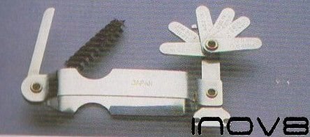
2. Car Plug Feeler Gauge and Adjuster tool
You may have a set of long feeler gauges but these do not have a lever notch for adjusting the plug gap Each feeler gauge has its thickness marked on the top. Maybe necessary, use two of the gauges together to make up the thickness specified, if your feeler gauges do not have a gapping tool included, a small screwdriver will do the Job instead. A long-bustled paint brush is also useful to clean away loose dirt around the plug seat.
Before pulling off the plug connector caps, label each plug's high-tension lead with its cylinder number so that it can be replaced correctly. Then pull off the plug caps always pull the cap itself, not the plug leads. Push the plug spanner firmly on to the first plug and unscrew it about four turns Use the paint Brush to clean out any. dirt or flakes of corrosion from around the plug hole to prevent them from falling inside the cylinder when toe plug is out. Some cars have a particularly deep plug recess where a brush will not go - either blow out the dirt or use a vacuum cleaner to remove it. Unscrew the plug completely and repeat
The procedure for all the other plugs bearing mind that if the engine is still hot, the plugs will be too. Do not use too much force if you have a stubborn spark plug. an extension steel handle of the plug spanner to get more leverage. If this does not work, take the car to a service garage which will the looks and experience to do the Job. Garages can repair damaged plug hole with a spring like steel insert essential if the plug has been cross threaded into cylinder head. look at the colour and condition of the tip of each spark plug if the engine is well tuned all the plugs should be the same.
 |
 |
| 3. Car plug colour | 4. Car plug worn |
light biscuity brown colour (fig 3). Plugs of a significantly different appearance are a sign of a problem needing further investigation You may have a leak between the inlet manifold and the head or a burnt valve.
Marked rounding of the centre electrode together with pitting of the side electrode (fig 4) means that the plug should be discarded. it is not a good idea to renew just one plug - always fit a whole new set.
Badly blackened spark plugs or those with hard deposits can be cleaned by grit blasting never use a wire brush on the tip of the plug because the bristles can leave conductive tracks of metal across the centre electrode insulator. Some garages will grit blast plugs for a small charge but compare their charge with the cost of new plugs before you go ahead because the slaving may be insignificant. There is also a DIY plug cleaner that works in the same way as the professional machine. You can clean off any soft, dusty deposits with a tooth- brush. A wire brush can be used to remove any dirt from the screw threads of the plug (fig 5). Wipe off any dust or oil on the ceramic insulator body.

5. Clean Car Plug with brush
Next, use the contact file to clean the tip of the central electrode and the inside face of the side electrode. If the file will not fit between the electrodes, use the lever notch on the gapping tool to bend back the side electrode slightly File the surfaces of the electrodes until they are clean and flat be careful to keep the file level while you are using it.
Most cars have a plug gap of about 0.025in in (0.6-0.7 mm). but the gap recommended for your car should be given in your manual pick the feeler gauge of the correct thickness and use it to measure the gap between the electrodes the feeler gauge should be a tight sliding fit without any slop at all once it fitted between the electrodes
You can adjust the gap by bending the side electrode (fig 6). If the gap is too narrow. bend back the side electrode with the lever notch on the gapping tool. If the gap is' too wide tap the side electrode with the lever notch on the gapping tool if the gap is to wide tap the side electrode gently with a spanner so that it moves closer to the central electrode. Always check that new spark plugs have the right gap.
6. Car Plug Adjustment
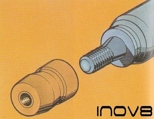
A Light smear of graphite grease on the plug threads (fig 7) will make them easier to screw In and help to prevent them seizing up.
 .
.
7. Car Plug Grease
However, plugs which are too greasy can cause bad running so give the insulators a final wipe before you screw them in (fig 8) Screw the plug into the hole by hand for at least the first four turns so that there can be no of cross-threading.

8. Clean Plug Before Replacing in car
Plugs should never be over-tightened they must-only be screwed down hard enough to make a good gas seal then if the plug has if the plug has a metal compression gasket, screw it down by a further quarter of a turn. if the plug ha a taper seat, screw it down by only one sixteenth of a turn.
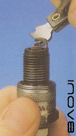
Before you reconnect the plug leads, note the type of terminal connection on the top of the plug, There are two types, Some plug caps push home directly on to the thin screw thread which protrudes from the ceramic insulator while others fit over a much thicker adapter which screws on to the plug terminal (fig 9) Depending on which type of lead connector you have, you may have either to remove or to screw on this collar. Push the plug caps firmly home over the plug-top terminals. Make sure you have the plug leads on the right plug by checking that the labels off the leads are in order. Finally, check your work by running the engine and make sure that it idles smoothly without any of the lumpiness that would suggest that one cylinder is not firing.
9. Car Plug Srew On cap
- Details
- Parent Category: Maintenance Guide
- Category: Electrical & electronic
Motor car Guide to Classic Car alternator sevice & overhaul
Replace Internal Brushes
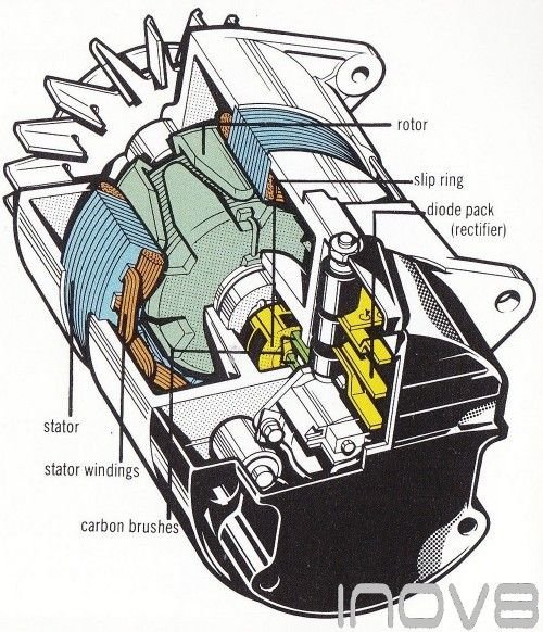
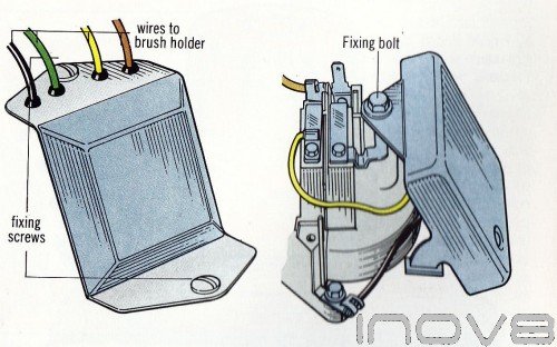
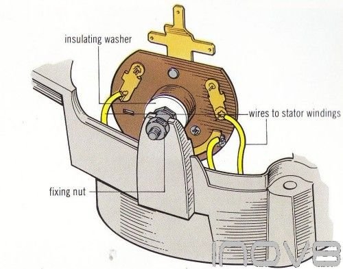
Except for the Lucas ACR series, most alternators with internal brushes are difficult to dismantle and can only be repaired by an auto electrician. On ACR types, use a socket spanner to undo the two recessed bolts which hold the black slip ring cover (fig 1). Make a note or draw a diagram of the wiring (fig 2) and then disconnect the connection from the brush holder to the diode pack.
 |
 |
| 1 Undoing the slip ring cover | 2 Types of voltage regulator connections |
Then undo the screws which hold the brush holder and the surge diode to the alternator casing (fig 3) - some ACR models also have a screw holding the voltage regulator to the casing - and lift the brush holder away (fig 4). Undo the small bolts holding the bushes to the brush holder making a note of the positions of the wires to the regulator (fig 2). pull the brushes out of the holder (fig 5)
 |
 |
| 3 Unscrew the alternator brush holder | 4 Lift away the brush holder |
The brush nearest the centre should have a small flat spring fitted along- side it. Check the length of the brushes (fig 6) and if they are less than 3/16 in. (5 mm) in length buy some new ones. Clean the holder with meths and then fit the new brushes into place remembering to fit the flat spring suppled with the brushes (fig 7). replace the small bolts that hold the brushes. together with any wires that were under them Now reassemble the unit.
 |
 |
 |
| 5 Pulling out the brushes | 6 compare new & old brushes | 7 Rember the spring |
Change a ACR voltage regulator
The only alternator with an internal regulator which can be easily dismantled the Lucas ACR type, -The regulator is a sealed transistorized unit so it cannot be repaired if it is faulty you will need a new one, There are several different types of regulator and it is best to take the old one to your dealer to make sure you get the right one, If the original type of regulator is not available your dealer will be able to offer an alternative type which will fit, To remove the regulator, first undo the slip ring cover and find the regulator screws. Some models have two screw one to the alternator body and one to the brush holder (fig 1) - others are held by one screw on to the brush holder (fig I), Draw a diagram of the regulator connections and then remove them. Undo the screws and lift the regulator away, Fit the new regulator into place and reconnect all the leads. finally refit the slip ring cover.
Voltage regulator fixings
Renew the acr slip ring
Check the surface of the slip ring for glazing or wear. If the copper surface of the slip ring looks dull - as if coated with varnish - you should clean it with abrasive paper. Take care not to allow grit or dust to fall inside the unit. When the copper slip ring is smooth and bright give it a wipe with a rag soaked in meths. If the slip ring IS badly worn, scored or holed it should be replaced as it will wear out the brushes very quickly. With the brush holder removed, undo the three bolts which hold the front and rear casings of the alternator together (fig 1). Carefully pull the two brackets apart - the rotor and slip ring come off with the front bracket and the diode pack and stator windings come off with the rear bracket. Support the alternator firmly and then unsolder the two wires on the side of the slip ring (fig 2). If you do not want to do this part of the job, strip the alternator yourself and take it to an auto electrician to have the soldering done. These are firmly attached so you may have to apply the soldering iron for some time before the solder starts to melt. The slip ring will heat up while unsoldering so use a rag to pull it off the top of the rotor shaft, or you may burn yourself. Push the new slip ring on to the rotor shaft making sure that the small spring clip is in place and that the pip inside the slip ring hole locates in the groove on the end of the rotor shaft. Solder the wires into their grooves on the slip ring but do not use too much solder on the join - ‘it may foul on the diode pack when you reassemble the alternator. When reassembling the unit make sure the ventilation slots in the slip ring cover are clear and then refit it to the alternator. Now refit the unit
 |
 |
| 1 Removing the alternator through bolts | 2 The 2 wires that need to be unsoldered |
Renew the ACR Diode pack
The diode pack, or rectifier, is, bolted to the rear bracket of the alternator. It is connected to the windings by three wires which are soldered in place, so to change the pack the wires must be unsoldered. If you do want to solder, save money stripping the unit yourself d then taking it to an auto electrician to have the soldering done Make a note of where the three wires go (fig 1) and then unsolder each one - use', a pair of long-nosed pliers to grip the Wire as close to the diode pack as possible. Apply the soldering iron to the terminals for a few seconds until the wire comes loose and quickly pull the wire outwards away from the terminal. With all three wires removed undo the nut holding the diode pack to the alternator (fig 1). Some types are also held inside the casing by an extra nut and racket, so remove this, if fitted. As you lift the pack out notice the position of the washers and the small. black rubber cap. These must be transferred to the new pack before fitting it. place the new diode pack into position and tighten up the securing nut. Fit the three wires to their terminals, and solder them into position. Do not keep the soldering iron on the terminal for more than a few seconds at a time the diode pack has delicate components that are easily damaged. Again, use the long-nosed pliers to grip the wires as this will help conduct the heat away.
Diode Pack Held in by a nut it has 3 wires
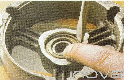
Check the bearings for wear
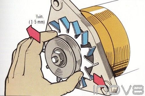
An alternator which is noisy in operation usually has worn bearings. If the noise is only slight then it is probably not worth doing anything about, but a loud rattling or ‘graunching' nose should not be ignored. To check the front bearing for wear, hold the alternator firmly and spin the pulley - it should rotate smoothly, any roughness or grinding noise means that the bearing is worn. Also try to rock the pulley from side to side (fig 1) - very slight movement is acceptable, so long as the bearing does not sound rough but if the play is more than 1/16 in, (1,5 mm) then the bearing must be replaced the rear bearing is more difficult to check as the alternator casings have to be separated (see Step 4) to get at it. Once you have separated the alternator casings, check the bearing by spinning it. It should not feel rough or make a grinding noise in practice the rear bearing seldom wears as it. has very little load, unlike the front bearing and is well protected from dirt by the alternator casing,
Test Front bearing play on a car alternator
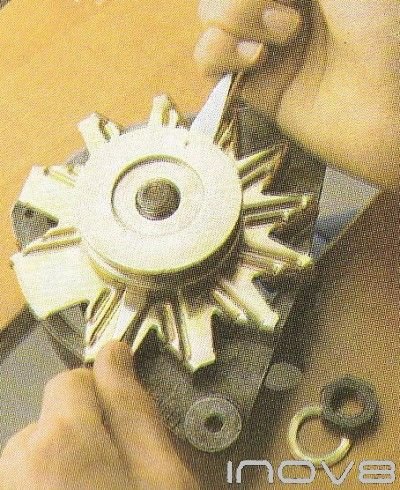
Remove The Rotor
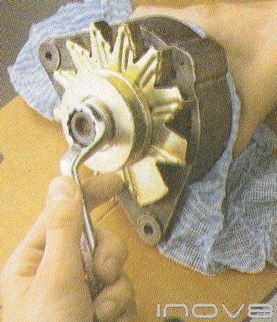
The rotor has to be removed before the front bearing can be changed. To remove it, hold the rotor tightly and undo the nut on the end of the shaft (fig 1). This is often very tight use rags or wear a pair of rubber gloves to get some extra grip. Take off the spring washer and put it safely to' one side. Using two flat-bladed screwdrivers
 |
 |
| 1 Undoing the rotar nut | 2 Lever of pulley |
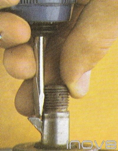
lever the pulley off the shaft (fig 2). If it is tight do not be tempted to use a lot of force you may crack or bend the pulley. if it will not budge you will have to use a puller on it, Once the pulley is off you can remove the cooling fan.Rotate the fan until the cut-out slot lines up with the Woodruff key and then pull it off. Use a pair of pliers to remove the Woodruff key if it is stuck, carefully prise it out with a screwdriver (fig 3) - and put it somewhere safe. Take off the spacer ring (fig 4) which holds the fan clear of the front bracket and put it safely
 |
|
| 3 Prising out woodruff key | 4 Dont forget this spacer |
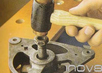
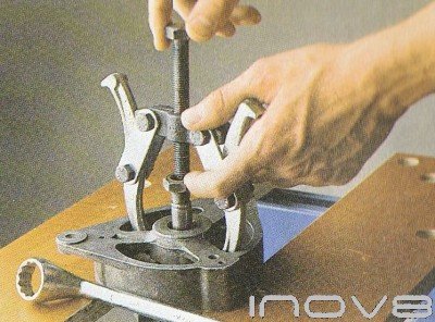
With the Woodruff key. Position the front bracket on the edge of a sturdy table or workbench Make sure the rotor is not fouling on the edge of the bench and then put the pully nut back on the end of the shaft, with a copper or hide- headed mallet drive the rotor out of the front bracket (fig 5). If the rotor shows no sign of moving do not carry on hitting the end of the shaft - all you will do is damage the nut and the threads. Instead use a two- or three-legged puller on the end of the shaft to’ pull the front racket from the rotor assembly (fig 6). With the legs of the puller in place hold on to the rotor and tighten up the nuts or bolts on the puller, making sure it does not slip off.
 |
 |
| 5 Tap rotor out with mallet | 6 using a Puller on front alternator bracket |
Renew The Front Bearing
The front bearing in an alternator is a ball bearing race very similar to the ones used in dynamos. These are sealed-for- life units so once dirt has entered the bearing it will wear out quickly. Apart from an over- tightened drive belt, the main cause of bearing failure is dirt getting past a damaged seal. The bearing is held in by a circlip which locates in a groove in the front bracket. Hold a rag over the circlip and prise it out with a long, flat-bladed screw driver (fig 1). Do this carefully a's the circlip is very springy. With the circlip removed the bearing is simply pushed out If it sticks use a socket and hammer .to tap it out. Make a note of the position of washer’s spacers or seals (fig 2).
 |
|
| 1 Prising out the circlip with a screwdriver | 2 New bearing with spacers washers & seals |
Reassembly is quite straight forward. Fit the new seal and bearing into the front bracket, gently tapping them into place if necessary. Once the bearing is properly seated push the circlip back into its groove with two screwdrivers. This requires patience as it is a fiddly job but it will go in eventually. Refit the bracket to the rotor by tapping the front bracket with a soft-headed mallet. Alternatively, use a press to fit the rotor into the bracket.
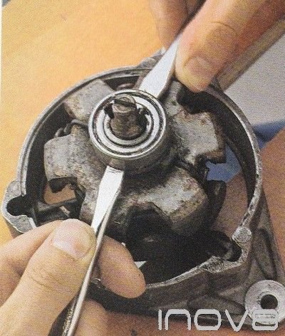
Renew The Rear Bearing
To change the rear bearing, separate the two casings of the alternator and remove the slip ring Then using two screwdrivers carefully try to lever the bearing off the rotor shaft (fig 1). If it is very tight you will have to use a bearing puller to remove it or have it removed by an auto electrician. Fit the new barn by tapping it into place on the rotor shaft using a socket as a drift (fig 2). Refit the slip ring and reassemble the alternator
 |
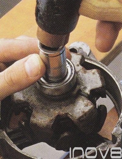 |
| 1 Lever of bearing with screwdriver | 2 tapping on the new bearing |
© Motor Car History
- Details
- Parent Category: Maintenance Guide
- Category: Electrical & electronic
Electrical System Circuit Light Test Checker

A Simple test light is used to check the continuity of an electrical circuit a basic cheap test solution.
How to use a test light on an electrical circuit.
A test light utilizes a bulb held in a probe attached to a sharply pointed rod with a grounding lead. This design is optimal for piercing a wire, testing a fuse or checking the surface charge of a battery. A test light is easy to use, first connect the ground clip to a known good ground source, the battery negative terminal is best but any grounded metal source will work.
Then connect the pointed end of the test light to desired circuit to be tested.
If power is present the bulb will illuminate informing you the circuit has power and is operating properly. Also, you can reverse the test light lead to the positive battery to be able to check for system ground continuity.
Note: A test light should be used for basic electrical circuits only. Do not use a test light to check computer related circuits, a voltmeter should be used in these cases.
- Details
- Parent Category: Maintenance Guide
- Category: Electrical & electronic
Car Ignition Switch Stuck Wont Turn
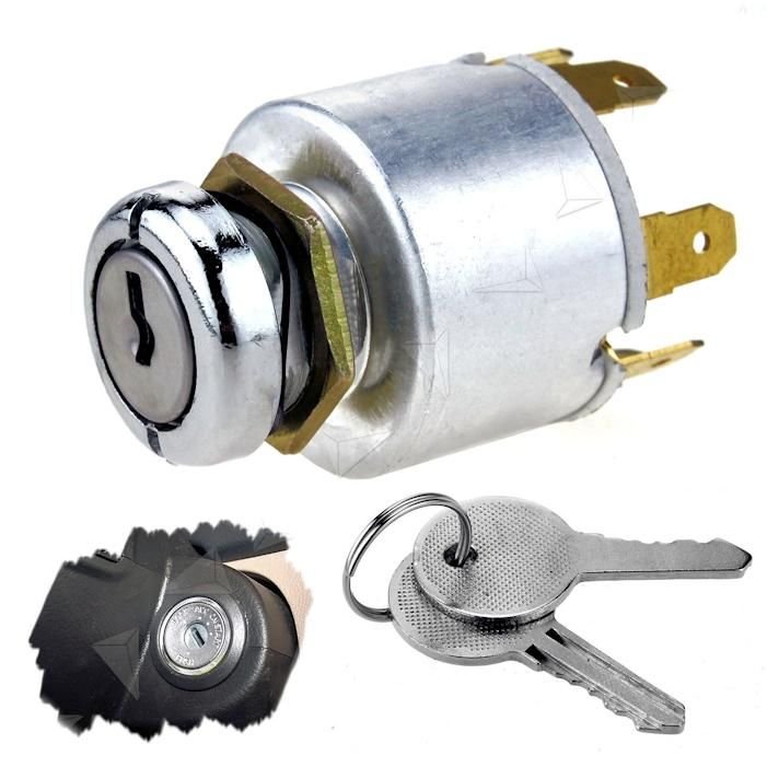
An ignition switch is designed to utilize a key that controls the main electrical switch in your car This switch controls the engine starter, main control systems and other various systems. The key is used to keep unwanted users from operating the vehicle. This key and lock are much like any other lock and key assembly. All lock assemblies have a periodical maintenance schedule. This lock service includes cleansing of the key and internal lock assembly.
After the cleaning maintenance has been performed a small amount of lock lubricant should be added to the internal lock tumbler. The car ignition lock is subject to pressures and vibration through normal usage. When this condition occurs, the key switch will not operate, this could mean the switch will need to be replaced. There are various other conditions can cause the ignition switch not to turn; we have listed the most common ones below.
Troubleshooting an Ignition Switch That Won’t Turn
Step 1 - Most modern cars have power steering; the power steering sometimes uses hydraulic pressure to assist the driver in steering the car. When the engine is shut off the hydraulic pressure is relieved. If the steering wheel is turned when the car is shut off the "lock pin" that holds the steering wheel in one place is now under pressure. Place your hand on the steering wheel and pull it in one direction and then the other while turning the ignition switch. This should normally release the lock pin from inside and allow the switch to operate properly. (Note: always shut the car engine off when the steering wheel is in the straight position)
Step 2 - Dirt and debris inside the key lock can cause the tumbler assembly to malfunction by not allowing one or more of the key followers to operate. Protect your eyes and use pressurized air to clean the internal lock mechanism. Next, clean the key with a mild detergent and dry. Then use a lock lubricant and move the key in and out of the lock tumbler while trying to turn it.
Step 3 - The ignition key is designed to hold the key followers in the correct place to allow the cylinder to turn. If the teeth of the key wear down it will not operate the lock properly. Try your spare key in the lock, if a spare key works the lock, have copies made of that key and discard the key that doesn't work anymore unless this is chipped always keep.
Step 4 - A car with an automatic transmission utilizes an interlock cable that holds the car in park when the key is in the off position. If the gear shift selector is not completely in park it can cause the ignition switch to malfunction. Check the gear selector to make sure it is completely in the park position.
Step 5 - The ignition switch has many components; on some vehicles the actual ignition switch is down on the steering column and connects the key and tumbler by a mechanism. If this mechanism or the switch fails it could cause the key switch not to turn. To repair this problem, disassemble the steering column and repair or replace the broken parts as needed then reassemble and recheck.
- Details
- Parent Category: Maintenance Guide
- Category: Electrical & electronic
ECU Remapping for Volvo

Guide to possible BHP and Torgue improvement, on Volvo cars with ECU remapping or upgrade.
| Model | Variant | Original BHP | Tuning Performance |
| 440 | 1.7 T | 120 BHP | Stage 1: ECU Remap +35 BHP +72 Nm Torque |
| 440 | 1.8 | 89 BHP | Stage 1: ECU Remap +11 BHP +22 Nm Torque |
| 440 | 2.0 | 110 BHP | Stage 1: ECU Remap +13 BHP +24 Nm Torque |
| 460 | 1.7 T | 120 BHP | Stage 1: ECU Remap +35 BHP +72 Nm Torque |
| 460 | 1.8 | 89 BHP | Stage 1: ECU Remap +11 BHP +22 Nm Torque |
| 460 | 2.0 | 110 BHP | Stage 1: ECU Remap +13 BHP +24 Nm Torque |
| 480 | 1.8 | 89 BHP | Stage 1: ECU Remap +11 BHP +22 Nm Torque |
| 480 | 2.0 | 110 BHP | Stage 1: ECU Remap +13 BHP +24 Nm Torque |
| 740 | 2.3 T | 170 BHP | Stage 1: ECU Remap +40 BHP +75 Nm Torque |
| 740 | 2.3 T | 190 BHP | Stage 1: ECU Remap +40 BHP +75 Nm Torque |
| 850 | 2.0 | 126 BHP | Stage 1: ECU Remap +13 BHP +24 Nm Torque |
| 850 | 2.0 | 143 BHP | Stage 1: ECU Remap +13 BHP +24 Nm Torque |
| 850 | 2.4 | 144 BHP | Stage 1: ECU Remap +13 BHP +24 Nm Torque |
| 850 | 2.4 | 170 BHP | Stage 1: ECU Remap +13 BHP +24 Nm Torque |
| 850 | 2.4 T | 193 BHP | Stage 1: ECU Remap +35 BHP +35 Nm Torque |
| 850 | 2.5 TDi | 140 BHP | Stage 1: ECU Remap +34 BHP +40 Nm Torque |
| 850 | 2.3 R | 250 BHP | Stage 1: ECU Remap +35 BHP +80 Nm Torque |
| 850 | 2.3 T5 | 225 BHP | Stage 1: ECU Remap +50 BHP +100 Nm Torque |
| 850 | 2.3 TR5 | 240 BHP | Stage 1: ECU Remap +35 BHP +80 Nm Torque |
| 850 | 3.0 R | 250 BHP | Stage 1: ECU Remap +35 BHP +80 Nm Torque |
| 940 | 2.0 T | 155 BHP | Stage 1: ECU Remap +32 BHP +69 Nm Torque |
| 940 | 2.3 T | 135 BHP | Stage 1: ECU Remap +35 BHP +50 Nm Torque |
| 940 | 2.3 T | 165 BHP | Stage 1: ECU Remap +35 BHP +50 Nm Torque |
| 940 | 2.4 T | 122 BHP | Stage 1: ECU Remap +35 BHP +35 Nm Torque |
| 960 | 2.3 T | 165 BHP | Stage 1: ECU Remap +35 BHP +50 Nm Torque |
| C30 | 2.0 D | 136 BHP | Stage 1: ECU Remap +30 BHP +70 Nm Torque |
| C30 | 2.4 D5 | 180 BHP | Stage 1: ECU Remap +30 BHP +60 Nm Torque |
| C30 | 2.5 T5 | 225 BHP | Stage 1: ECU Remap +29 BHP +39 Nm Torque |
| C70 | 2.0 | 126 BHP | Stage 1: ECU Remap +15 BHP +15 Nm Torque |
| C70 | 2.0 T | 163 BHP | Stage 1: ECU Remap +32 BHP +69 Nm Torque |
| C70 | 2.4 T | 193 BHP | Stage 1: ECU Remap +35 BHP +35 Nm Torque |
| C70 | 2.4 D5 | 180 BHP | Stage 1: ECU Remap +30 BHP +50 Nm Torque |
| C70 | 2.4 T5 | 240 BHP | Stage 1: ECU Remap +35 BHP +80 Nm Torque |
| S40 | 1.6 | 109 BHP | Stage 1: ECU Remap +12 BHP +14 Nm Torque |
| S40 | 1.8 | 122 BHP | Stage 1: ECU Remap +14 BHP +15 Nm Torque |
| S40 | 1.8 DI | 125 BHP | Stage 1: ECU Remap +15 BHP +17 Nm Torque |
| S40 | 1.9 D | 115 BHP | Stage 1: ECU Remap +30 BHP +50Nm Torque |
| S40 | 1.9 D | 102 BHP | Stage 1: ECU Remap +20 BHP +46 Nm Torque |
| S40 | 1.9 TD | 90 BHP | Stage 1: ECU Remap +30 BHP +35 Nm Torque |
| S40 | 1.9 TDi | 90 BHP | Stage 1: ECU Remap +30 BHP +35 Nm Torque |
| S40 | 1.9 T4 | 200 BHP | Stage 1: ECU Remap +33 BHP +54 Nm Torque |
| S40 | 2.0 D | 136 BHP | Stage 1: ECU Remap +30 BHP +70 Nm Torque |
| S40 | 2.0 T | 160 BHP | Stage 1: ECU Remap +32 BHP +69 Nm Torque |
| S40 | 2.4 D5 | 180 BHP | Stage 1: ECU Remap +30 BHP +60 Nm Torque |
| S40 | 2.5 T5 | 220 BHP | Stage 1: ECU Remap +29 BHP +39 Nm Torque |
| S60 | 2.0 T | 180 BHP | Stage 1: ECU Remap +30 BHP +80 Nm Torque |
| S60 | 2.4 D | 130 BHP | Stage 1: ECU Remap +60 BHP +110 Nm Torque |
| S60 | 2.4 T | 200 BHP | Stage 1: ECU Remap +35 BHP +81 Nm Torque |
| S60 | 2.5 T | 210 BHP | Stage 1: ECU Remap +35 BHP +40 Nm Torque |
| S60 | 2.4 D5 | 163 BHP | Stage 1: ECU Remap +30 BHP +60 Nm Torque |
| S60 | 2.3 T5 | 250 BHP | Stage 1: ECU Remap +30 BHP +73 Nm Torque |
| S60 | 2.4 T5 | 260 BHP | Stage 1: ECU Remap +35 BHP +76 Nm Torque |
| S70 | 2.0 | 126 BHP | Stage 1: ECU Remap +13 BHP +24 Nm Torque |
| S70 | 2.5 TDi | 140 BHP | Stage 1: ECU Remap +34 BHP +40 Nm Torque |
| S70 | 2.3 R | 250 BHP | Stage 1: ECU Remap +34 BHP +40 Nm Torque |
| S70 | 2.4 | 140 BHP | Stage 1: ECU Remap +13 BHP +24 Nm Torque |
| S70 | 2.4 | 170 BHP | Stage 1: ECU Remap +13 BHP +24 Nm Torque |
| S70 | 2.3 T5 | 240 BHP | Stage 1: ECU Remap +35 BHP +80 Nm Torque |
| S70 | 2.4 T | 193 BHP | Stage 1: ECU Remap +35 BHP +50 Nm Torque |
| S70 | 2.5 TDi | 140 BHP | Stage 1: ECU Remap +34 BHP +40 Nm Torque |
| S80 | 2.0 T | 180 BHP | Stage 1: ECU Remap +30 BHP +80 Nm Torque |
| S80 | 2.4 T | 200 BHP | Stage 1: ECU Remap +35 BHP +35 Nm Torque |
| S80 | 2.4 TDi | 140 BHP | Stage 1: ECU Remap +34 BHP +40 Nm Torque |
| S80 | 2.4 D5 | 163 BHP | Stage 1: ECU Remap +31 BHP +60 Nm Torque |
| S80 | 2.5 TDi | 140 BHP | Stage 1: ECU Remap +34 BHP +40 Nm Torque |
| S80 | 2.5 T | 210 BHP | Stage 1: ECU Remap +35 BHP +40 Nm Torque |
| S80 | 2.8 T6 | 272 BHP | Stage 1: ECU Remap +40 BHP +62 Nm Torque |
| S90 | 2.9 | 180 BHP | Stage 1: ECU Remap +13 BHP +24 Nm Torque |
| S90 | 2.9 | 204 BHP | Stage 1: ECU Remap +13 BHP +24 Nm Torque |
| V40 | 1.6 | 109 BHP | Stage 1: ECU Remap +12 BHP +14 Nm Torque |
| V40 | 1.8 | 122 BHP | Stage 1: ECU Remap +14 BHP +15 Nm Torque |
| V40 | 1.8 Di | 125 BHP | Stage 1: ECU Remap +15 BHP +17 Nm Torque |
| V40 | 1.9 D | 116 BHP | Stage 1: ECU Remap +8 BHP +46 Nm Torque |
| V40 | 1.9 D | 102 BHP | Stage 1: ECU Remap +20 BHP +46 Nm Torque |
| V40 | 1.9 D | 90 BHP | Stage 1: ECU Remap +33 BHP +46 Nm Torque |
| V40 | 1.9 TD | 90 BHP | Stage 1: ECU Remap +30 BHP +35 Nm Torque |
| V40 | 1.9 T | 160 BHP | Stage 1: ECU Remap +33 BHP +54 Nm Torque |
| V40 | 1.9 T4 | 200 BHP | Stage 1: ECU Remap +29 BHP +39 Nm Torque |
| V40 | 2.0 T | 160 BHP | Stage 1: ECU Remap +32 BHP +39 Nm Torque |
| V40 | 2.0 | 136 BHP | Stage 1: ECU Remap +13 BHP +24 Nm Torque |
| V50 | 2.0 D | 136 BHP | Stage 1: ECU Remap +30 BHP +70 Nm Torque |
| V50 | 2.4 D5 | 180 BHP | Stage 1: ECU Remap +30 BHP +60 Nm Torque |
| V50 | 2.5 T5 | 225 BHP | Stage 1: ECU Remap +35 BHP +40 Nm Torque |
| V70 | 2.0 | 126 BHP | Stage 1: ECU Remap +13 BHP +24 Nm Torque |
| V70 | 2.0 T | 180 BHP | Stage 1: ECU Remap +32 BHP +69 Nm Torque |
| V70 | 2.4 | 140 BHP | Stage 1: ECU Remap +13 BHP +24 Nm Torque |
| V70 | 2.4 | 170 BHP | Stage 1: ECU Remap +13 BHP +24 Nm Torque |
| V70 | 2.4 T | 250 BHP | Stage 1: ECU Remap +35 BHP +75 Nm Torque |
| V70 | 2.4 T | 200 BHP | Stage 1: ECU Remap +35 BHP +60 Nm Torque |
| V70 | 2.4 T | 193 BHP | Stage 1: ECU Remap +35 BHP +60 Nm Torque |
| V70 | 2.4D5 | 163 BHP | Stage 1: ECU Remap +31 BHP +80 Nm Torque |
| V70 | 2.5 T | 210 BHP | Stage 1: ECU Remap +34BHP +65 Nm Torque |
| V70 | 2.5 TDi | 140 BHP | Stage 1: ECU Remap +34 BHP +40 Nm Torque |
| V70 | 2.5 TR | 265 BHP | Stage 1: ECU Remap +29 BHP +35 Nm Torque |
| V70 | 2.3 T5 | 240 BHP | Stage 1: ECU Remap +35 BHP +80 Nm Torque |
| V70 | 2.4 T5 | 260 BHP | Stage 1: ECU Remap +35 BHP +76 Nm Torque |
| V90 | 2.9 | 180 BHP | Stage 1: ECU Remap +13 BHP +24 Nm Torque |
| V90 | 2.9 | 204 BHP | Stage 1: ECU Remap +13 BHP +24 Nm Torque |
| XC60 | 2.4 D5 | 185 BHP | Stage 1: ECU Remap +37 BHP +80 Nm Torque |
| XC70 | 2.4 D5 | 163 BHP | Stage 1: ECU Remap +32 BHP +80 Nm Torque |
| XC70 | 2.4 T | 200 BHP | Stage 1: ECU Remap +35 BHP +35 Nm Torque |
| XC70 | 2.5 T | 210 BHP | Stage 1: ECU Remap +34BHP +65 Nm Torque |
| XC90 | 2.5 T | 210 BHP | Stage 1: ECU Remap +34BHP +65 Nm Torque |
| XC90 | 2.4 D5 | 185 BHP | Stage 1: ECU Remap +37 BHP +80 Nm Torque |
| XC90 | 2.4 D5 | 163 BHP | Stage 1: ECU Remap +32 BHP +80 Nm Torque |
| XC90 | 2.8 T6 | 272 BHP | Stage 1: ECU Remap +40 BHP +62 Nm Torque |